
For automotive technicians and car enthusiasts alike, the OBD II scanner has become an indispensable tool. Celebrating over two decades since its introduction, OBD II technology continues to empower us with critical insights into vehicle health. While many understand its basic fault code reading capabilities, the real power of a generic OBD II scanner often lies untapped in its ability to monitor live data – particularly fuel trim. This article delves deep into the diagnostic potential of “Obd Ii Scanner Fuel Trim,” guiding you to leverage this data for pinpointing a wide array of driveability issues with enhanced precision.
The significance of fuel trim data was underscored in training initiatives like the Robert Bosch-sponsored mobile training vehicles. These programs challenged technicians to diagnose virtual vehicle problems, emphasizing a structured approach starting with OBD II data. The process consistently highlighted the importance of fuel trim baselining as a crucial early step, right after verifying the customer’s complaint, retrieving fault codes, and performing a preliminary visual inspection.
Baselining fuel trim data is a straightforward yet powerful four-step diagnostic procedure:
- Connect an OBD II Scanner: Utilize a generic OBD II scan tool, ideally one equipped with data recording capabilities for later analysis.
- Monitor and Record Fuel Trim Values: Observe and record short-term fuel trim (STFT) and long-term fuel trim (LTFT) values across four key engine operating ranges:
- Idle Speed
- Light Load (20 to 30 mph)
- Moderate Load (40 to 50 mph)
- Heavy Load (60 to 70 mph)
- Analyze the Collected Data: Scrutinize the recorded fuel trim values to identify patterns and deviations from expected behavior.
- Target Subsequent Diagnostic Steps: Based on the fuel trim analysis, strategically direct your subsequent diagnostic procedures to the most probable components or systems.
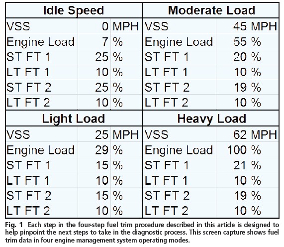
Fig. 1: Fuel trim data recorded on a vehicle displaying lean system fault codes P0171 and P0174. This data is crucial for guiding diagnostic direction beyond generic fault code descriptions.
Consider the fuel trim data presented in Fig. 1, captured from a vehicle with the check engine light illuminated and fault codes P0171 (Bank 1 System Lean) and P0174 (Bank 2 System Lean) registered. Standard troubleshooting guides for these codes often suggest a broad spectrum of potential culprits, ranging from a clogged fuel filter or failing fuel pump to vacuum leaks or a contaminated mass airflow (MAF) sensor. Fig. 2 illustrates a typical Gasoline Direct Injection (GDI) system layout, showcasing the multitude of sensors and actuators that could potentially be involved. Notably, the vehicle in our example is a V-engine configuration, indicating the presence of multiple upstream oxygen sensors – one for each bank.
Fig. 2: A typical GDI system layout highlighting common engine management sensors and actuators. Understanding system components is essential for effective fuel trim diagnosis.
Faced with these fault codes and the fuel trim data from our four-step process, the crucial question arises: Which component or system, as depicted in Fig. 2, should be prioritized for testing? In simulated diagnostic scenarios, technicians often gravitate towards checking for intake leaks using a smoke machine, driven by the commonality of this issue. However, in the presented case, this path would lead to a diagnostic dead end as no intake leaks were present.
Why did so many technicians initially opt to check for intake leaks? The prevalent rationale is that intake leaks are a frequent problem and technicians often prefer to rule out the common issues first. While not inherently wrong, this approach in this specific scenario is not supported by the fuel trim data.
Re-examining the fuel trim data in Fig. 1 is paramount. The data reveals a critical pattern: the lean condition is evident across both banks and throughout all operating ranges – idle, light load, moderate load, and heavy load. This consistent lean indication across all driving conditions significantly alters the diagnostic direction.
Considering this, how does an intake air leak align with the observed fuel trim data? Fig. 3 illustrates typical fuel trim behavior in vehicles with intake air leaks. Characteristically, fuel trim values are elevated at idle and tend to normalize or “clean up” as engine speed and load increase. While MAF sensor-equipped vehicles might exhibit slightly elevated fuel trims at higher operating ranges due to unmetered air, the magnitude is usually not sufficient to trigger P0171 or P0174 codes. In the example of Fig. 3, the fuel trim values are not high enough to cause these lean codes.
Fig. 3: Fuel trim data indicative of intake air leaks. Note the high fuel trim at idle that diminishes at higher operating ranges, a pattern distinct from the all-range lean condition in Fig. 1.
Returning to Fig. 2 and reconsidering our diagnostic strategy, we must identify components that can influence fuel trim values consistently across all operating ranges. The MAF sensor, the low-pressure fuel pump, and potentially the GDI high-pressure pump emerge as the prime suspects.
While leaking fuel injectors are often cited as potential causes for P0171/P0174, their effect on fuel trim is opposite. Leaking injectors result in a richer-than-normal air-fuel mixture, driving fuel trim values negative and potentially triggering rich codes like P0172/P0175 (Bank 1 and 2 Rich). Clogged injectors should be considered, but after evaluating the components highlighted above.
Further refinement of our diagnostic focus hinges on a deeper understanding of how each of these suspect components interacts with fuel trim. Let’s consider the low-pressure fuel pump first. As suggested earlier, a clogged fuel filter, a worn fuel pump, or generally low fuel pressure can indeed lead to P0171/P0174. The primary consequence would be insufficient fuel volume reaching the GDI high-pressure pump.
Insufficient fuel supply to the high-pressure pump would prevent the powertrain control module (PCM) from achieving and maintaining the desired fuel rail pressure, which is dynamically adjusted based on operating conditions. The fuel pressure sensor (FPS) provides feedback to the PCM on the actual rail pressure. At idle and light loads, the demand on the low-pressure pump is lower, whereas increased loads necessitate higher rail pressure and greater fuel volume delivery.
A crucial point to consider: If the PCM detects that the desired fuel pressure is not being met, what fault code is typically set? In GDI systems, a P0087 (Fuel Rail System Pressure Too Low) is the more probable code, rather than P0171/P0174, in cases of low fuel pressure.
While our example uses a GDI system, the fundamental principles extend to port fuel injected vehicles. The low-pressure fuel pump’s volume delivery characteristics remain similar – lower volume at idle, higher volume under load. Depending on the severity of a low-pressure fuel pump issue, fuel trims might be mildly elevated at idle but worsen significantly with increasing load. In severe cases, fuel trim deviations would be substantial enough to trigger fault codes and noticeably impair vehicle performance.
However, the fuel trim data from Fig. 1, exhibiting significant adjustment across all operating ranges, strongly points towards the MAF sensor. The MAF sensor’s role is to measure the volume of air entering the engine, a critical parameter used by the PCM to calculate the correct injector pulse width for optimal air-fuel ratio. In our lean condition example, the PCM is compensating by increasing injector pulse width to enrich the mixture and achieve the desired air-fuel ratio.
How do we effectively test the MAF sensor? Again, the OBD II scanner provides the necessary data. Fig. 4 presents MAF sensor data showing a reading of 2.0 grams/second (g/S) at idle, against a specified range of 2.00 to 5.00 g/S at idle under normal operating temperature. While service information specifications are valuable, they are not always perfectly precise and may require refinement in real-world diagnostics. For the 2.5L GDI engine in our example, a more accurate target idle MAF reading would be approximately 2.5 g/S. This indicates the MAF sensor is underreporting airflow by about 20%, directly correlating with the positive fuel trim values observed at idle.
Fig. 4: MAF sensor data showing a low reading at idle (2.0 g/S) compared to the expected range (2.00-5.00 g/S), suggesting an underestimation of airflow and contributing to lean fuel trims.
To comprehensively assess MAF sensor performance across all operating ranges, recording MAF sensor data during a wide-open throttle (WOT) acceleration test and comparing it against a volumetric efficiency (VE) chart or calculator is recommended. These resources are readily available online and provide a benchmark for expected airflow based on engine parameters.
In the case vehicle, a dirty MAF sensor was indeed the culprit, underestimating airflow across all operating ranges and triggering the P0171/P0174 codes. While the MAF sensor was listed as a potential cause in generic troubleshooting, understanding fuel trim data allowed for a more directed and efficient diagnostic process, moving beyond simply guessing at potential issues.
Utilizing fuel trim effectively in vehicle diagnostics is a skill honed through practice and a thorough understanding of component interactions. Consider the purge solenoid, illustrated in Fig. 1. Under normal operation, the purge solenoid remains closed, and the PCM periodically commands it open to purge fuel vapors from the charcoal canister. At idle, intake manifold vacuum is present on the engine side, while the vapor side should be near atmospheric pressure. The vapor load in the canister varies based on factors like recent refueling and ambient temperature. If the purge solenoid were stuck open, in which operating range would fuel trim be most significantly affected? The answer is idle. Critically, fuel trim deviations could be either positive or negative depending on the vapor concentration within the charcoal canister.
Fig. 5: Fuel trim response to purge solenoid activation at idle. The blue trace shows solenoid command, while the green trace (STFT) demonstrates a rapid negative shift indicating rich vapor purging, followed by a positive shift as vapor depletes and a vacuum leak effect dominates.
Fig. 5 demonstrates the impact of purge solenoid activation on idle fuel trim (blue trace indicating solenoid command, green trace representing STFT). Around 13.65 seconds, STFT rapidly shifts negative, reaching -30%, signifying a rich vapor purge from the canister. Approximately 40 seconds later, just before 54.6 seconds, STFT begins to move positively, indicating vapor depletion and the emergence of a vacuum leak effect. Once the purge solenoid is commanded closed again, STFT returns to near zero.
The key takeaway is that a fuel trim recording showing a predominant issue at idle might point towards a stuck-open purge solenoid. Crucially, the STFT values can fluctuate between positive and negative depending on the vapor load. The purge solenoid’s influence diminishes significantly at higher engine loads.
Fig. 6: Fuel trim behavior on a late-model Dodge Charger with a induced vacuum leak. Note the STFT (red and green traces) flatlining at +32.8% for an extended period before LTFT adjustment occurs, illustrating vehicle-specific fuel trim strategies.
Two additional points enhance our understanding of fuel trim interpretation. First, vehicle-specific fuel trim strategies vary. Some vehicles initiate long-term fuel trim (LTFT) adjustments as soon as short-term fuel trim (STFT) reaches a defined limit, causing STFT to drift back towards zero. Other vehicles exhibit a more delayed LTFT response. Fig. 6, from a late-model Dodge Charger with an induced vacuum leak, illustrates this. STFT flatlines at +32.8% for an extended four-minute period before LTFT begins to compensate. This highlights that understanding vehicle-specific fuel trim behavior is crucial.
Second, many European vehicle applications utilize distinct “additive” and “multiplicative” fuel trim strategies, often accessible via enhanced scan tools. “Additive” trim reflects adjustments at idle or just off idle, while “multiplicative” trim indicates adjustments at higher RPM and vehicle speeds. When monitoring generic OBD II data parameters (STFT and LTFT), it’s important to recognize that these values will react independently across different operating ranges.
By now, the diagnostic power inherent in monitoring fuel trim values using an OBD II scanner should be evident. Embracing the four-step fuel trim procedure and practicing on both known-good vehicles and those with induced faults is invaluable for developing proficiency. Experiment by intentionally creating faults, such as disconnecting the purge solenoid hose, and observe the resulting fuel trim patterns across different operating ranges. Furthermore, systematically analyze each component depicted in Fig. 2 and contemplate how its malfunction would manifest in fuel trim data.
Even after two decades, generic OBD II data, particularly fuel trim, remains an incredibly potent tool, empowering technicians to efficiently and accurately resolve common driveability issues.