
The On-Board Diagnostic system, or OBD2, is your vehicle’s silent informant, constantly monitoring its health and performance. Since its standardization, OBD2 has become an indispensable tool for mechanics, car enthusiasts, and everyday drivers alike. Understanding OBD2 and utilizing an effective OBD2 scanner, like a Gord Obd 2 Scanner, can empower you to diagnose issues, optimize performance, and even save money on repairs.
This comprehensive guide will delve into the world of OBD2, explaining everything from its fundamental principles to its advanced applications. We’ll explore the OBD2 connector, Parameter IDs (PIDs), communication protocols like CAN bus, and, importantly, how a GORD OBD 2 Scanner can be your key to unlocking your vehicle’s hidden data. Whether you’re a seasoned mechanic or just curious about what’s under the hood, this guide will provide you with the knowledge to confidently navigate the realm of OBD2 diagnostics.
You can also watch our OBD2 intro video above – or get the PDF
What Exactly is OBD2?
OBD2 is essentially your car’s built-in health monitoring system. It’s a standardized protocol that allows access to crucial information about your vehicle’s operation. Think of it as a universal translator, enabling diagnostic tools, like the GORD OBD 2 Scanner, to communicate with your car’s computer. Through the OBD2 connector, you can retrieve Diagnostic Trouble Codes (DTCs) and real-time data, providing valuable insights into your vehicle’s condition.
Have you ever seen the check engine light illuminate on your dashboard? That’s OBD2 in action, signaling that your car has detected a problem. When you take your car to a mechanic, one of the first tools they’ll reach for is an OBD2 scanner. This tool connects to the OBD2 16-pin connector, usually located near the steering wheel. The scanner sends “OBD2 requests” to the car’s computer, and the computer responds with “OBD2 responses.” These responses can include everything from speed and engine temperature to fuel levels and, most importantly, those Diagnostic Trouble Codes (DTCs). By interpreting this data, mechanics can quickly pinpoint issues, making troubleshooting faster and more efficient, especially when using a reliable scanner like the GORD OBD 2 Scanner.
Understanding the Malfunction Indicator Light (MIL) as a key indicator of OBD2 system alerts.
Is My Car OBD2 Compatible?
The good news is, if you own a relatively modern car, the answer is almost certainly yes!
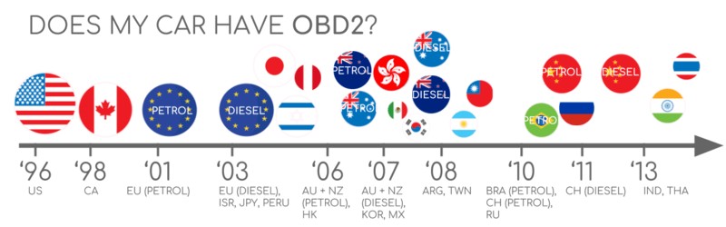
Nearly all non-electric cars manufactured in recent decades support OBD2, and most utilize the CAN bus communication protocol. However, it’s worth noting that some older vehicles might have a 16-pin OBD2 connector but may not fully support the OBD2 protocol. Compliance is generally linked to the vehicle’s market and manufacturing date:
A helpful infographic illustrating OBD2 compliance based on region and vehicle type.
A Brief History of OBD2
The story of OBD2 begins in California. The California Air Resources Board (CARB), driven by environmental concerns, mandated OBD in all new cars sold in California from 1991 onwards for emissions control.
The Society of Automotive Engineers (SAE) played a crucial role in standardizing OBD2, defining DTCs and the universal OBD connector (SAE J1962). This standardization was a game-changer, making diagnostic tools like the GORD OBD 2 Scanner universally applicable across different vehicle manufacturers.
The OBD2 standard was implemented globally in phases:
- 1996: OBD2 became mandatory in the USA for cars and light trucks.
- 2001: The European Union mandated OBD2 for gasoline cars (EOBD).
- 2003: EOBD was extended to diesel cars in the EU.
- 2005: OBD2 became required in the US for medium-duty vehicles.
- 2008: US vehicles were mandated to use ISO 15765-4 (CAN) as the foundation for OBD2 communication.
- 2010: OBD2 compliance was extended to heavy-duty vehicles in the US.
A visual timeline highlighting the evolution of OBD2 and its focus on emission control.
A timeline showcasing the key milestones in OBD2’s development and global adoption.
An illustration depicting the potential future of OBD systems, including remote diagnostics and IoT integration.
The Future of OBD2: Trends and Transformations
While OBD2 remains a cornerstone of vehicle diagnostics, its future is evolving, driven by new vehicle technologies and connectivity demands.
Initially designed for emissions testing, legislated OBD2 isn’t strictly required for electric vehicles (EVs). Interestingly, most modern EVs don’t support standard OBD2 requests. Instead, they often use OEM-specific UDS communication protocols. This can make accessing data from EVs challenging, except when reverse engineering efforts reveal decoding methods, as seen in case studies for brands like Tesla, Hyundai/Kia, Nissan, and VW/Skoda EVs.
Limitations in data richness and lower-layer protocols in traditional OBD2 have spurred the development of alternatives. WWH-OBD (World Wide Harmonized OBD) and OBDonUDS (OBD on UDS) are emerging standards aimed at modernizing OBD communication by utilizing the UDS protocol. These advancements promise enhanced diagnostic capabilities and data access, potentially influencing future generations of OBD2 scanners, including the GORD OBD 2 Scanner.
In our increasingly connected world, manual OBD2 emission checks seem outdated. The concept of OBD3 envisions adding telematics to vehicles. OBD3 would incorporate a radio transponder in cars, enabling the wireless transmission of the Vehicle Identification Number (VIN) and DTCs to a central server for automated monitoring.
Many current devices already facilitate wireless OBD2 data transfer via WiFi or cellular networks, exemplified by tools like the CANedge2 WiFi CAN logger and CANedge3 3G/4G CAN logger. This offers convenience and cost savings but raises valid concerns about data privacy and surveillance.
The original purpose of OBD2 was for in-shop servicing. However, third-party access to OBD2 data has become widespread for real-time data generation through OBD2 dongles, CAN loggers, and more. Interestingly, there’s a push from some in the automotive industry to restrict this third-party access. The argument centers around security and preventing unauthorized access that could lead to car hacking. However, many view this as a commercially motivated move to control automotive data. Whether this trend gains traction remains to be seen, but it could significantly impact the market for third-party OBD2 services and devices.
A visual representation of the potential shift in data access with electric vehicles and the OBD2 connector.
Become a CAN Bus Expert with our ‘Ultimate CAN Guide’
Want to delve deeper into the world of vehicle communication networks?
Our comprehensive 160+ page PDF guide provides 12 easy-to-understand introductions to CAN bus and related technologies.
Download now
Understanding OBD2 Standards
On-board diagnostics, OBD2, operates as a higher-layer protocol, similar to a language, built upon communication methods like CAN bus, which is akin to a phone line. This hierarchical structure positions OBD2 alongside other CAN-based protocols like J1939, CANopen, and NMEA 2000.
OBD2 standards comprehensively define the OBD2 connector, lower-layer communication protocols, OBD2 Parameter IDs (PIDs), and more.
These standards can be visualized using the 7-layer OSI model. Notably, both SAE (US standards) and ISO (EU standards) cover various layers, reflecting the global harmonization efforts in OBD2. Many standards are technically very similar, such as SAE J1979 and ISO 15031-5, and SAE J1962 and ISO 15031-3.
The OSI model illustrating the relationship between OBD2 and CAN bus standards and protocols.
A detailed pinout diagram of a Type A OBD2 connector, highlighting its standardized interface.
The OBD2 Connector: SAE J1962 Standard
The 16-pin OBD2 connector provides a standardized and easy way to access your car’s diagnostic data. It is defined by the SAE J1962 / ISO 15031-3 standards.
The illustration above shows a typical Type A OBD2 pin connector, also known as the Data Link Connector (DLC).
Key features of the OBD2 connector include:
- Its location is usually near the steering wheel, though it might be somewhat hidden depending on the vehicle model.
- Pin 16 provides battery power, often even when the ignition is off, allowing scanners to operate.
- The OBD2 pinout configuration depends on the communication protocol used by the vehicle.
- CAN bus is the most prevalent lower-layer protocol, meaning pins 6 (CAN-H) and 14 (CAN-L) are commonly connected.
OBD2 Connector Types: A vs. B
In practice, you might encounter both Type A and Type B OBD2 connectors. Type A is generally found in cars, while Type B is more common in medium and heavy-duty vehicles.
While both types share similar pinouts, they differ in power supply output (12V for Type A and 24V for Type B) and often baud rates. Cars typically use 500K baud rate, while heavy-duty vehicles often use 250K (with increasing support for 500K).
Visually, Type B connectors have an interrupted groove in the middle, distinguishing them from Type A. A Type B OBD2 adapter cable is generally compatible with both Type A and Type B sockets, while a Type A adapter will not fit into a Type B socket. When choosing an OBD2 scanner, like a GORD OBD 2 Scanner, consider the connector type compatibility with your vehicle.
A comparison of Type A and Type B OBD2 connectors, highlighting differences in power and application.
A diagram emphasizing the relationship between OBD2 and CAN bus within the ISO 15765 framework.
OBD2 and CAN Bus: ISO 15765-4
Since 2008, CAN bus has been the mandatory lower-layer protocol for OBD2 in all US-sold vehicles, as defined by ISO 15765.
ISO 15765-4 (Diagnostics over CAN, or DoCAN) specifies constraints on the CAN standard (ISO 11898) to ensure interoperability for diagnostic equipment.
Specifically, it standardizes the CAN interface for test equipment, focusing on the physical, data link, and network layers:
- CAN bus bit-rates must be either 250K or 500K.
- CAN IDs can be 11-bit or 29-bit.
- Specific CAN IDs are designated for OBD requests and responses.
- Diagnostic CAN frame data length is fixed at 8 bytes.
- The OBD2 adapter cable length must not exceed 5 meters.
OBD2 CAN Identifiers: 11-bit and 29-bit
OBD2 communication is based on a request-response message structure.
In most cars, 11-bit CAN IDs are used for OBD2. The ‘Functional Addressing’ ID, 0x7DF, is used to query all OBD2-compatible ECUs for data on a requested parameter (ISO 15765-4). ‘Physical Addressing’ requests, using CAN IDs 0x7E0-0x7E7, can target specific ECUs but are less common.
ECUs respond with 11-bit IDs in the range 0x7E8-0x7EF. The most frequent response ID is 0x7E8 (from the Engine Control Module, ECM), followed by 0x7E9 (from the Transmission Control Module, TCM).
Some vehicles, particularly vans and medium to heavy-duty vehicles, use 29-bit CAN identifiers for OBD2.
Here, the ‘Functional Addressing’ CAN ID is 0x18DB33F1.
Responses use CAN IDs ranging from 0x18DAF100 to 0x18DAF1FF, typically 18DAF110 and 18DAF11E. The response ID is sometimes represented as a J1939 PGN (Parameter Group Number), specifically PGN 0xDA00 (55808), which is reserved for ISO 15765-2 in the J1939-71 standard. Understanding these identifiers is crucial when using advanced OBD2 tools like the GORD OBD 2 Scanner for in-depth diagnostics.
A visual representation of OBD2 request and response frames, illustrating data flow and parameters.
A diagram contrasting OBD2 standard CAN bus communication with OEM-specific proprietary protocols.
OBD2 vs. Proprietary CAN Protocols
It’s important to understand that your car’s Electronic Control Units (ECUs) operate using proprietary CAN protocols defined by the Original Equipment Manufacturer (OEM), independently of OBD2. These OEM-specific protocols are often unique to the vehicle brand, model, and year. Interpreting this proprietary data is generally not possible without OEM-specific tools or reverse engineering.
Connecting a CAN bus data logger to the OBD2 connector might reveal OEM-specific CAN data, typically broadcast at high rates (1000-2000 frames/second). However, many newer vehicles incorporate a ‘gateway’ that blocks access to this proprietary CAN data via the OBD2 port, allowing only OBD2 communication.
Essentially, OBD2 is an additional, higher-layer protocol operating alongside the OEM-specific communication network within your vehicle. While a GORD OBD 2 Scanner excels at interpreting OBD2 data, accessing deeper, OEM-specific data might require specialized tools and knowledge.
Bit-rate and ID Validation
OBD2 can utilize two bit-rates (250K, 500K) and two CAN ID lengths (11-bit, 29-bit), resulting in four potential combinations. Modern cars commonly use 500K and 11-bit IDs. Diagnostic tools should systematically validate these parameters to ensure correct communication.
ISO 15765-4 outlines a systematic initialization sequence for determining the correct combination. This process relies on the fact that OBD2-compliant vehicles must respond to a mandatory OBD2 request (see the OBD2 PID section) and that incorrect bit-rates will cause CAN error frames.
Newer versions of ISO 15765-4 account for OBD communication via OBDonUDS alongside OBDonEDS. This article primarily focuses on OBD2/OBDonEDS (OBD on Emission Diagnostic Service as per ISO 15031-5/SAE J1979) versus WWH-OBD/OBDonUDS (OBD on Unified Diagnostic Service as per ISO 14229, ISO 27145-3/SAE J1979-2).
To differentiate between OBDonEDS and OBDonUDS, diagnostic tools can send UDS requests with 11-bit/29-bit functional address IDs for service 0x22 and data identifier (DID) 0xF810 (protocol identification). Vehicles supporting OBDonUDS should have ECUs that respond to this DID.
In practice, OBDonEDS (also known as OBD2, SAE OBD, EOBD, or ISO OBD) is prevalent in most non-EV cars today, while WWH-OBD is primarily used in EU trucks and buses. A GORD OBD 2 Scanner is designed to handle these protocol variations, ensuring broad compatibility.
A flowchart illustrating the process of OBD2 bit-rate and CAN ID validation as per ISO 15765-4.
A visual overview of the five lower-layer OBD2 protocols, showcasing their evolution and standards.
Five Lower-Layer OBD2 Protocols
While CAN bus (ISO 15765) is now dominant for OBD2, particularly in vehicles from 2008 onwards, older cars may utilize other lower-layer protocols. Understanding these protocols can be helpful when diagnosing older vehicles. The OBD2 connector pinout can sometimes provide clues about the protocol in use.
- ISO 15765 (CAN bus): Mandatory in US cars since 2008 and most common today.
- ISO14230-4 (KWP2000): Keyword Protocol 2000, common in 2003+ cars, especially in Asia.
- ISO 9141-2: Used in EU, Chrysler, and Asian cars around 2000-2004.
- SAE J1850 (VPW): Primarily used in older GM vehicles.
- SAE J1850 (PWM): Primarily used in older Ford vehicles.
ISO-TP: Transporting OBD2 Messages Beyond 8 Bytes (ISO 15765-2)
All OBD2 data communication over CAN bus relies on ISO-TP (ISO 15765-2), a transport protocol that enables the transmission of messages exceeding the 8-byte CAN frame limit. This is essential for OBD2 functions like retrieving the Vehicle Identification Number (VIN) or Diagnostic Trouble Codes (DTCs), which often require larger payloads. ISO 15765-2 handles segmentation, flow control, and reassembly of these larger messages.
However, much of the standard OBD2 data fits within a single CAN frame. In these cases, ISO 15765-2 specifies the use of ‘Single Frame’ (SF) messages. The first data byte (PCI field) indicates the payload length (excluding padding), leaving 7 bytes for OBD2-specific data. Advanced scanners like the GORD OBD 2 Scanner are designed to handle both single-frame and multi-frame OBD2 communication seamlessly.
Illustrations of ISO-TP frame types used in OBD2 communication, including Single Frame, First Frame, Consecutive Frame, and Flow Control Frame.
Decoding the OBD2 Diagnostic Message: SAE J1979, ISO 15031-5
To understand OBD2 communication on CAN, let’s examine a simplified ‘Single Frame’ OBD2 CAN message. An OBD2 message comprises an identifier, a data length indicator (PCI field), and the data itself. The data section is further structured into Mode, Parameter ID (PID), and data bytes.
A breakdown of the OBD2 message structure, showing the arrangement of Mode, PID, and data bytes within a CAN frame.
OBD2 Request/Response Example: Vehicle Speed
Consider a practical example: requesting and receiving vehicle speed data.
A diagnostic tool, such as a GORD OBD 2 Scanner, sends a request message to the car with CAN ID 0x7DF and two payload bytes: Mode 0x01 and PID 0x0D (for Vehicle Speed). The car responds with a message via CAN ID 0x7E8 and three payload bytes. The vehicle speed value is encoded in the fourth byte, in this example, 0x32 (decimal 50).
By consulting the OBD2 PID documentation for 0x0D, we can determine that the value 0x32 corresponds to a physical speed of 50 km/h. This illustrates the fundamental request-response mechanism of OBD2 and how PIDs are used to access specific data points.
A sequence diagram illustrating an OBD2 request for Vehicle Speed (PID 0x0D) and the corresponding response.
A detailed look at OBD2 PID 0x0D, Vehicle Speed, showing its data encoding and interpretation.
An overview of the 10 standardized OBD2 service modes, highlighting their diagnostic functions.
The 10 OBD2 Services (Modes)
OBD2 defines 10 diagnostic services, also referred to as modes. Mode 0x01 is used for accessing real-time data, while other modes are designed for retrieving and clearing Diagnostic Trouble Codes (DTCs), accessing freeze frame data, and more.
It’s important to note that vehicles are not required to support all 10 OBD2 modes. They may also implement OEM-specific modes beyond the standardized set.
In OBD2 messages, the service mode is indicated in the second byte. In a request message, the mode is included directly (e.g., 0x01). In the response message, 0x40 is added to the requested mode (e.g., a response to mode 0x01 will start with 0x41). Understanding these modes is key to effectively using an OBD2 scanner.
OBD2 Parameter IDs (PIDs)
Within each OBD2 service mode, Parameter IDs (PIDs) are used to specify the data being requested or provided.
For instance, mode 0x01 includes approximately 200 standardized PIDs for real-time data such as speed, RPM, and fuel level. However, vehicles typically support only a subset of these PIDs within mode 0x01.
One PID holds special significance: mode 0x01 PID 0x00. If an emissions-related ECU supports any OBD2 services, it must support mode 0x01 PID 0x00. Responding to this PID, the ECU indicates its support for PIDs 0x01-0x20. This makes PID 0x00 a fundamental tool for verifying OBD2 compatibility. Similarly, PIDs 0x20, 0x40, and so on, are used to determine support for subsequent ranges of mode 0x01 PIDs. A GORD OBD 2 Scanner often uses PID 0x00 as a starting point for system checks.
Reiteration of the OBD2 request-response frame structure, emphasizing the role of PIDs in data parameters.
A screenshot of an OBD2 PID overview tool, designed to simplify PID lookups and OBD2 data interpretation.
OBD2 PID Overview Tools
SAE J1979 and ISO 15031-5 appendices provide scaling information for standard OBD2 PIDs, enabling the conversion of raw data into physical values.
For quick lookups of mode 0x01 PIDs, online OBD2 PID overview tools are invaluable. These tools assist in constructing OBD2 request frames and dynamically decoding OBD2 responses, streamlining the diagnostic process when using tools like a GORD OBD 2 Scanner.
OBD2 PID overview tool
Practical Guide: Logging and Decoding OBD2 Data
Let’s walk through a practical example of logging OBD2 data using a CANedge CAN bus data logger. While CANedge is mentioned, the principles apply broadly to OBD2 logging and can be adapted for use with a GORD OBD 2 Scanner with data logging capabilities.
The CANedge, and similar loggers, allow configuration of custom CAN frames for transmission, making them suitable for OBD2 logging. Connecting the logger to your vehicle is straightforward using an OBD2-DB9 adapter cable.
A diagram depicting an OBD2 data logger initiating a PID request (0x7DF) and receiving a response (0x7E8).
Demonstrating a bit-rate validation test for OBD2 communication.
Screenshot from asammdf software showing OBD2 Supported PIDs test responses.
Step #1: Bit-rate, ID, and Supported PID Validation
As discussed earlier, ISO 15765-4 provides guidance on determining the correct bit-rate and IDs for a specific vehicle. You can perform these tests using a CANedge or a similar tool with transmit capabilities, and the steps are generally applicable to setting up a GORD OBD 2 Scanner for advanced logging if it supports custom configurations:
- Test Bit-rate: Send a CAN frame at 500K and check for successful transmission. If unsuccessful, try 250K.
- Use Correct Bit-rate: Use the identified bit-rate for all subsequent OBD2 communication.
- Request Supported PIDs: Send multiple ‘Supported PIDs’ requests (PID 0x00) and analyze the responses.
- Determine ID Type: Based on response IDs, determine whether the vehicle uses 11-bit or 29-bit CAN IDs for OBD2.
- Identify Supported PIDs: Analyze the response data to see which PIDs are supported by the vehicle.
Pre-configured setups are often available to automate these tests. Most 2008+ non-EV cars typically support 40-80 PIDs using a 500K bit-rate, 11-bit CAN IDs, and the OBD2/OBDonEDS protocol.
As illustrated in the asammdf GUI screenshot, multiple ECUs might respond to a single OBD request when using the functional address 0x7DF, as all OBD2/OBDonEDS-compliant ECUs must support service 0x01 PID 0x00. Note that the ECM ECU (0x7E8) often supports all PIDs supported by other ECUs, which can optimize bus load by directing subsequent requests specifically to the ECM using the ‘Physical Addressing’ CAN ID 0x7E0.
Step #2: Configuring OBD2 PID Requests
Once you’ve identified the supported PIDs, bit-rate, and CAN IDs for your vehicle, you can configure your data logger or GORD OBD 2 Scanner to request specific PIDs of interest.
Consider these factors when configuring your requests:
- CAN IDs: Switch to ‘Physical Addressing’ request IDs (e.g., 0x7E0) to minimize redundant responses if you’re targeting a specific ECU.
- Request Spacing: Introduce a delay of 300-500 ms between OBD2 requests. Overly frequent requests can overwhelm ECUs and lead to dropped responses.
- Power Management: Use triggers to stop transmitting requests when the vehicle is inactive to prevent battery drain, especially if the scanner remains connected when the car is off.
- Data Filtering: Implement filters to record only OBD2 responses if your vehicle also broadcasts OEM-specific CAN data, to keep your logs focused and manageable.
With these configurations, your device is ready to log raw OBD2 data.
An example configuration list of OBD2 PID requests for a CANedge data logger, illustrating PID selection and request parameters.
Visualization of decoded OBD2 data in asammdf software, showing data plots derived from a DBC file.
Step #3: DBC Decoding of Raw OBD2 Data
To analyze and visualize logged OBD2 data, you need to decode the raw data into human-readable ‘physical values.’
Decoding information is found in ISO 15031-5/SAE J1979 and online resources like Wikipedia. A readily available OBD2 DBC file simplifies DBC decoding in most CAN bus software tools. This DBC file can also be highly beneficial when used in conjunction with a GORD OBD 2 Scanner that supports custom DBC loading or data export for external analysis.
Decoding OBD2 data is more complex than standard CAN signal decoding because different OBD2 PIDs are transmitted using the same CAN ID (e.g., 0x7E8). Therefore, the CAN ID alone isn’t enough to identify the signals within the payload.
To resolve this, decoding must consider the CAN ID, OBD2 mode, and OBD2 PID. This form of multiplexing, termed ‘extended multiplexing,’ can be implemented in DBC files, enabling accurate interpretation of OBD2 data.
CANedge: Your OBD2 Data Logging Solution
The CANedge provides a streamlined solution for recording OBD2 data directly to an SD card (8-32 GB). Simply connect it to your vehicle via the OBD2 port to start logging. Data can then be decoded using free software/APIs and the provided OBD2 DBC file. While CANedge is highlighted here, remember that many OBD2 scanners, including advanced models like the GORD OBD 2 Scanner, offer similar data logging and export features.
OBD2 logger intro CANedge
Exploring OBD2 Multi-Frame Examples: ISO-TP in Action
OBD2 communication, as per ISO 15765-2, utilizes ISO-TP for all data exchange, including multi-frame messages. While single-frame examples are common, multi-frame communication is essential for larger data sets.
Multi-frame OBD2 interactions require flow control frames. A common practice is to transmit a static flow control frame approximately 50 ms after the initial request, as demonstrated in CANedge configuration examples. This flow control is crucial for reliable multi-frame data transfer and is a feature that more sophisticated OBD2 scanners, such as the GORD OBD 2 Scanner, handle automatically.
Analyzing multi-frame OBD2 responses necessitates CAN software/API tools that support ISO-TP, like the CANedge MF4 decoders.
An example of an OBD2 multi-frame request message, specifically for retrieving the Vehicle Identification Number (VIN).
Example 1: Retrieving the Vehicle Identification Number (VIN) via OBD2
The Vehicle Identification Number (VIN) is vital for telematics, diagnostics, and various vehicle-related applications. OBD2 mode 0x09 and PID 0x02 are used to request the VIN.
The diagnostic tool sends a Single Frame request with the PCI field (0x02), request service identifier (0x09), and PID (0x02).
The vehicle responds with a First Frame containing the PCI, length (0x014 = 20 bytes), mode (0x49, i.e., 0x09 + 0x40), and PID (0x02). Following the PID is the Number Of Data Items (NODI) byte (0x01 in this case), indicating a single VIN is being returned. The subsequent 17 bytes represent the VIN, which can be converted from HEX to ASCII.
Example 2: OBD2 Multi-PID Request (6x)
OBD2 allows requesting up to six mode 0x01 PIDs in a single request frame. The ECU responds with data for supported PIDs, omitting unsupported ones, potentially using multi-frame responses as needed.
This efficient method increases data acquisition frequency, but the signal encoding becomes specific to the request method, making generic OBD2 DBC files less useful. While technically feasible, this method is generally not recommended for practical data logging due to decoding complexity.
The multi-frame response structure is similar to the VIN example. However, the payload includes the requested PIDs and their corresponding data. PIDs are often ordered as requested, although this is not strictly mandated by the ISO 15031-5 standard.
Decoding such responses using generic DBC files is challenging. This approach introduces ‘extended multiplexing’ complexities, especially if sending multiple multi-PID requests. Custom scripts and recording request messages can help correlate requests and responses, but these methods can be difficult to scale and manage. For most users, simpler, single-PID requests are more practical, especially when using versatile tools like a GORD OBD 2 Scanner designed for ease of use.
Example 3: OBD2 Diagnostic Trouble Codes (DTCs) Retrieval
OBD2 mode 0x03, ‘Show stored Diagnostic Trouble Codes,’ is used to request emissions-related DTCs. The request doesn’t include a PID. Responding ECUs report the number of stored DTCs (possibly zero) and the DTCs themselves, with each DTC encoded in 2 bytes. Multi-frame responses are necessary when more than two DTCs are stored.
The 2-byte DTC value is structured according to ISO 15031-5/ISO 15031-6. The first two bits define the DTC ‘category,’ and the remaining 14 bits form a 4-digit hexadecimal code. Decoded DTC values can be looked up using OBD2 DTC lookup tools available online.
The example below shows a request to an ECU reporting six stored DTCs.
A visual guide to interpreting OBD2 Diagnostic Trouble Codes (DTCs) and their 2-byte structure.
Real-World Applications: OBD2 Data Logging Use Cases
OBD2 data logging from cars and light trucks has a wide range of applications:
Visual representation of OBD2 data logging in a car, highlighting its application in on-board diagnostics.
Car Data Logging for Optimization
OBD2 data can be leveraged to reduce fuel consumption, improve driving habits, test prototype components, and optimize insurance risk assessments. Tools like the GORD OBD 2 Scanner can be invaluable for collecting this data for analysis.
obd2 logger
Illustration of OBD2 real-time data streaming, emphasizing its use in vehicle diagnostics.
Real-time Car Diagnostics
OBD2 interfaces facilitate real-time streaming of vehicle data in a human-readable format, ideal for diagnosing vehicle issues on the spot. This capability is a core feature of many OBD2 scanners, including the GORD OBD 2 Scanner.
obd2 streaming
OBD2 data logging for predictive maintenance, showing its role in telematics and IoT applications.
Predictive Maintenance
IoT-enabled OBD2 loggers can monitor vehicle health in the cloud, enabling predictive maintenance to prevent breakdowns and optimize fleet management.
predictive maintenance
OBD2 logger as a vehicle ‘black box’ recorder, useful for insurance, warranty, and incident analysis.
Vehicle Black Box Recording
An OBD2 logger can function as a ‘black box’ for vehicles, recording critical data for incident analysis, insurance claims, and diagnostic forensics.
can bus blackbox
Do you have an OBD2 data logging use case in mind? We’re happy to discuss your needs and provide expert guidance!
Contact us
Explore more introductory guides in our guides section or download the comprehensive ‘Ultimate Guide’ PDF.
Ready to start logging and streaming OBD2 data?
Get your OBD2 data logger or scanner today! Consider exploring options like the GORD OBD 2 Scanner for your diagnostic needs.
Buy now Contact us
Recommended Resources
OBD2 DATA LOGGER: EASILY LOG & CONVERT OBD2 DATA
CANEDGE2 – PRO CAN IoT LOGGER
[